 |
|
|
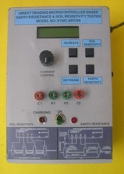
EARTH RESISTANCE & SOIL RESISTIVITY TESTER MODEL: ETMC-ERT/06 |
 |
|
|
|
* Earth Resistance made easy! Connect, Press and Read! * Microcontroller based with memory and programme. * Digital display of earth resistance at the press of a button. * Checks earth rods, earth mats, earth grids. * Optional: Soil Resistivity Measurement The Direct Reading Digital Earth Resistance Tester performs earth resistance measurements quickly and accurately at the press of a button. The equipment is based on the "fall of potential" method. Simply connect the two auxiliary electrodes and the earthing system under test, select the range, and directly read the measured resistance. This is the ideal instrument for electricity boards, industrial users, electrical contractors and others who must check earthing systems to determine compliance with statutory specifications. The Direct Reading Digital Earth Resistance Tester overcomes the limitations of conventional analog null balance earth testers commonly used. When stray currents/voltages are present, the needle of the analog null balance tester undergoes fluctuations and it is difficult to obtain a reading. The equipment overcomes this problem by measuring the value of the stray voltage and compensating for it in the internal calculations performed by its microcontroller circuits. In the case of the analog null balance tester, the operator has to keep changing the values of the resistances, till balance is obtained. The earth resistance reading is displayed on a 16x2 Character LCD at the press of a key, once connections are made. The equipment works on rechargeable batteries with built in charger circuits, unlike some analog null balance testers where the generator handle has to be rotated continuously. The equipment is not affected by the presence of AC voltages at 50 Hz and its harmonics. Test Procedure Make connections. Adjust current value with potentiometer knob keeping in mind to set high current value (that is maximum possible) when interference is high. Press first key. Now press the second key marked "earth resistance". the display flashes the word "WAIT" and in seconds displays the earth resistance value after internal computation. |
| Resolution | 0.01 ohm - 0.1 ohm |
| Display | 16x2 LCD Display |
| Power | (a) 12V, 4 Ah rechargeable batteries for powering the main unit. (b) Rechargeable batteries interface unit for driving the test current between the earthing system under test and the remote auxiliary current electrode. |
| Terminals | C,C: Black Terminals for connecting earthing system under test. B: Green Terminal for connecting auxiliary potential electrode (in between) A: Red Terminal for connecting auxiliary current electrode (remote) |
| Controls | (a) On / Off switch (b) Potentiometer control knob for setting the current. (c) Key for displaying earth resistance reading. (d) Key for displaying soil resistivity. (e) Key for increasing and decreasing the distance between the rods (used in soil resistivity measurement) |
| Operating Temperature | -10 degree C to 50 degree C |
| Dimensions | 540x340x140 mm (approx). |
| Weight | 7 kg (approx) |
| Accessories | Carry Case, Carry Bag, Auxiliary Rods - 2 Nos, Rolls of Wires - 2 Nos, Measuring Tape, Connecting Lead, Hammer. |